6 Shaft generator system using slip induction motor Nie Yansheng Liaoning 6,26 machine system of the Marine Engineering School of Dalian Maritime University, and a brief analysis of the structural characteristics and working principle of the system. It is pointed out that the advanced circuit forms and control methods used in such systems increase the difficulty of management and maintenance. When adopting such a system, energy conservation benefits and management and maintenance difficulties should be considered comprehensively.
From the perspective of energy saving, the use of a shaft generator system is a practical solution. The structure of the shaft generator system widely used in ships with large low-speed diesel engines directly driving the fixed-distance pulp.
Here, the shaft generator is installed between the main engine flywheel and the propeller shaft. The alternating current whose generator emits frequency changes with the change of the main engine speed, after rectification and inversion, the magnetic field oriented control pulse width modulation inverter is converted into an alternating current that meets the requirements. The output voltage of the system is regulated by the regulator of the synchronous compensator. At the same time, the synchronous compensator also provides reactive power and short-circuit current to the system. The excitation current of the shaft generator is provided by the thyristor rectifier for excitation. The control angle of the rectifier is changed to control the excitation current of the shaft generator, and the output power of the regulation system is similar to that of the brushless excitation phase generator. According to relevant information, in the field where the system output power is greater than 12001; this type of shaft generator system will still dominate the world shaft generator market. However, this type is optimal in the range of the system rated output power of about 500 kW. It is found that the loss generated by the synchronous compensator is relatively large. In addition, since the static frequency conversion device is in the main power supply circuit, the cost and volume are relatively large. To this end, Siemens has developed a shaft generator system using a slip induction motor, referred to as a shaft induction generator system 81, such as, port, 6, 131. This type of shaft generator system positioning In the field of application from 10O0kW to 500kW. Its purpose is to reduce costs and improve efficiency.
2 shaft with induction generator system structure characteristics and working principle shaft with induction generator system structure frame 2.
The reason why the diesel engine needs to drive the generator through the gear transmission mechanism is that the induction motor requires its air gap to be small, and the structural characteristics of the rotor core also determine the adoption of this method. In this way, a conventional machine can be used, thereby reducing costs and maintenance costs. The capacity and volume of the converter and system reactor are significantly reduced on the excitation circuit of the generator, rather than on the main supply circuit.
The inverter of the converter uses advanced pulse width modulation, which replaces the ordinary thyristor.
The gate can turn off the thyristor and have the function of a common thyristor, that is, a gate current pulse with a short duration can be applied, and the trigger can be turned on. After the conduction, the gate current can be maintained even if there is no gate current. On state. However, unlike ordinary thyristors, a negative gate anode voltage can be applied to turn off 1 . That is, when turned off, a considerable negative current flows through the gate. During the off time, this negative gate current, although only lasts for a few microseconds, must have a large amplitude. In the actual circuit, under the function of a controllable switch. In the inductive circuit, in order to reduce, 1 mountain on the anode when it is turned off, a buffer absorption circuit must be added at both ends of 0 â–¡ 0 to make the singer 1 at the time of shutdown to be as much as possible The low-bus-side converter circuit is two sets of phase-controlled bridges. The reverse-coupling method is used between them to ensure that the Shu-wave capacitor can replace the traditional smoothing reactor. On the motor side, in addition to the pulse width modulation inverter, a group feedback pole tube is added. Its function is to feed back the lag current to the filter capacitor and improve the stability of the inverter commutation work. The outstanding feature of the system is that the synchronous compensator is eliminated, so that the loss of the whole system can be reduced.
The relationship between the superposition principle and the physical properties of the induction motor can be derived. The voltage frequency unit of the 5 stator winding is the sub-division; the voltage frequency of the Fn rotor winding. The voltage frequency of the stator winding is the same as the voltage frequency of the grid, usually 601 or 502. The rotor rotation frequency of the rotor, 1 varies with the change of the host speed, so that 5 remains unchanged, only 0! Change ç›±, adjust the voltage frequency of the rotor winding Fn. The lexical law satisfies the equation Fn=Fsp.Fm. In the practice, the adjustment is realized by the pulse width modulation inverter circuit.
The pulse width modulation inverter is an on-off inverter. Since its DC side can be considered as a DC voltage source, it belongs to the class of voltage source inverters. There are many ways of pulse width modulation. In the inverter circuit, pulse width modulation such as equal pulse width modulation and sinusoidal pulse width modulation is the square wave control that turns on the voltage source inverter 180 to be divided into thousands of pulse control. The control signal is generated by a method in which an isosceles angular wave is referred to as a carrier and an adjustable DC voltage. The waveforms of its output voltage and current are both non-sinusoidal and have many subharmonic components. The difference between sinusoidal pulse width modulation and equal pulse width modulation is that the pulse width is sinusoidal. The carrier signal is still an angular wave and the reference signal is a sine wave. This way the output voltage will also change in a sinusoidal pattern. In this case, the lowest harmonic contained in the output voltage is twice the pulse frequency, which greatly reduces the harmonic content in the output voltage. A sinusoidal pulse width modulated inverter is used in the shaft induction generator system.
In order to realize sinusoidal pulse width modulation, it is necessary to calculate the time coordinates of all intersections of the reference signal sine wave and the carrier angular wave in real time, and according to the calculation result, the ON and OFF actions are sequentially issued to each 0 component in the inverter circuit. instruction. Therefore, in the sinusoidal pulse width modulation, the control part is composed of a Siemens control system 51 and a 5,0ç °è€µ module. The sequence and logic control functions are implemented by the 5550 programmable controller.
From a control point of view, the induction motor is a multivariable and mutually coupled nonlinear object, for which vector control techniques are employed. Vector control plays a significant role in decoupling and linearization. The basic idea of ​​vector control is to decompose the stator current of the motor along the motor flux axis into two components, the parallel component and the vertical component. The component parallel to the magnetic flux axis is corresponding to the magnetic field current component of the motor, which is used to generate the magnetic field of the motor; it is divided into two types perpendicular to the magnetic flux axis, and the magnetic field oriented control type is the rotor magnetic pole position orientation control. Field oriented control is used in this system. The so-called field oriented control is to take the real axis of the rotating coordinate system on the magnetic field axis and rotate synchronously with the magnetic field. For example, the rotor magnetic field axis is taken as the real axis, which is called the rotor field oriented control; if the stator magnetic field axis is taken as the real axis, it is called the stator field oriented control. This control idea was first proposed by engineers of Siemens in 1971, and has been widely used in AC variable frequency speed regulation.
3 Conclusion According to the above, we can easily find that the shaft generator system developed by Siemens adopts the advanced technology and achievements obtained in the research of AC speed control system, and is the modern AC variable speed control computer control and The perfect combination of advanced achievements in power electronics. Its advanced nature is unquestionable. The technologies and components used have been proven in land-based control systems, so there is no technical question in estimating the reliability of actual ship use. The more prominent question is how to maintain and manage this advanced system. Although Siemens is developing this system from the perspective of energy saving, as a ship owner, the use of such a shaft generator system is likely to be due to It is difficult for the wheel management personnel to effectively manage their maintenance, resulting in increased maintenance costs exceeding the benefits of their energy savings. In other words, it is not worth the candle. The emergence of such a system is not only a challenge for the wheel crew, but also a challenge for those engaged in training for crew training and navigation. Knowledge update and broadening of knowledge is not only a question that ship management personnel must face. The inverter inverter is still in a state where the trigger pulse is blocked, and the inverter cannot work. When the shaft generator system is shut down, 027 = the start of the 037 shaft generator system can not be carried out by the startup program control program. Only when 0矣6, only 037=0, the program can be completed and the startup process is completed. Therefore, it is ensured that the inverter does not fail due to excessive inverter angle during operation of the inverter.
Adjust the position of the moving square wave 025, and adjust the lower limit amplitude of the output of the inverter angle adjuster, which can be adjusted by Huang Jun. Semiconductor converter technology. Mechanical Industry Press, the 1984 staff who received the first page of training and maritime higher education must also face this question, and the requirements are more and more urgent.
1 Xu Yingen. AC speed control system and its application. The textile industry came out 2 Nie Yansheng. A microcomputer controlled shaft generator system. world
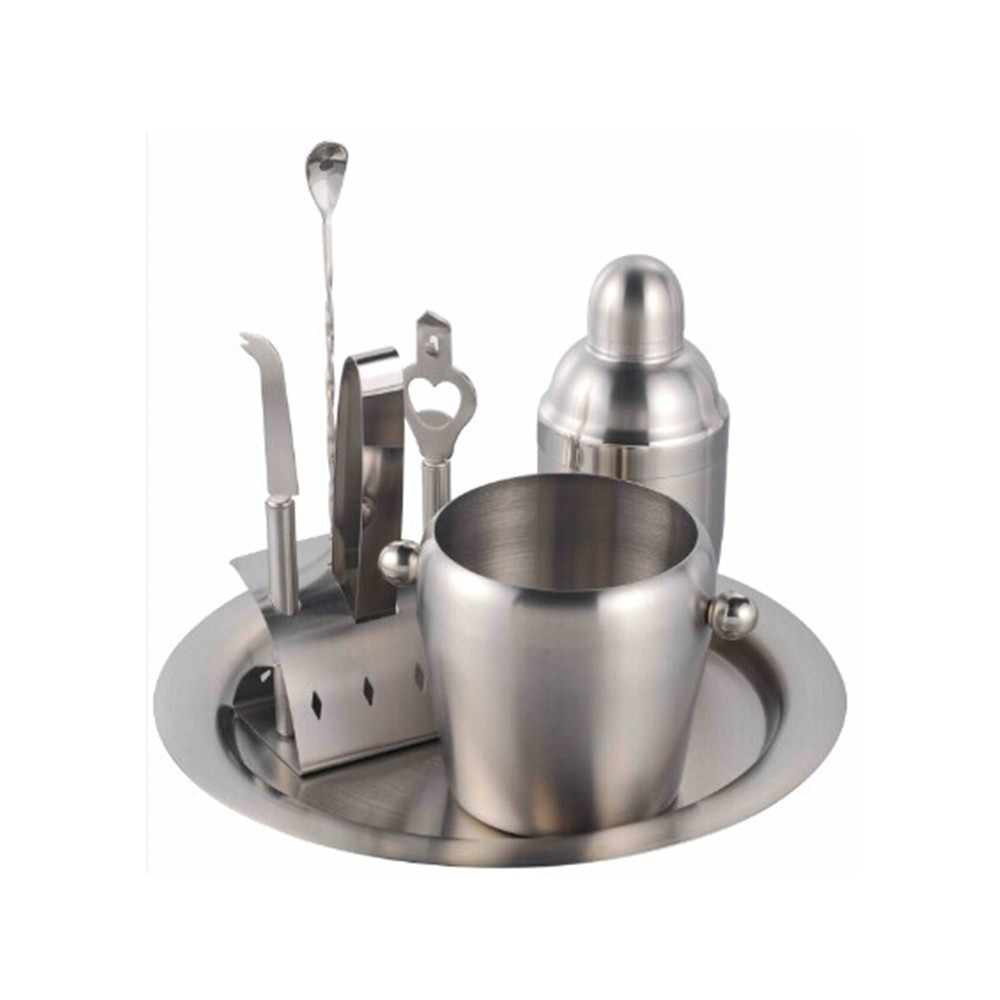
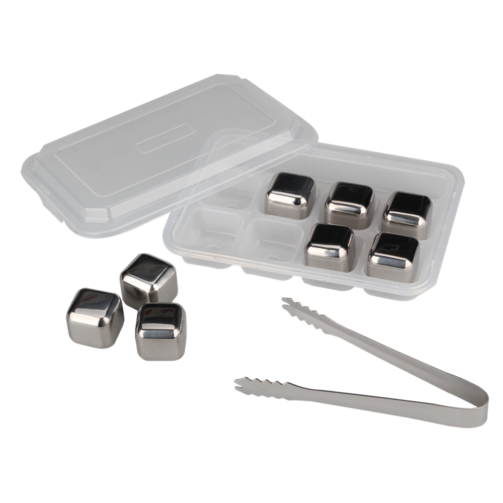
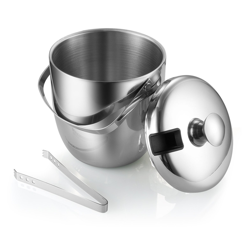
Stainless Steel Barware
We have many different kinds of barware items for you to choose, which made of excellent quality stainless steel material.
Cocktail shaker set suitable to use in home and bar for cocktail making, combine different kinds of cocktail tools, such as cocktail shaker, ice tong, knife, bottle open, strainer, Measuring Cup and so on.
High quality whiskey stone ,help you enjoy the wine and keep cold. Different shape for you to choose, coffee bean, diamonds ball , bullet shape and so on.
Material:SS304
Finishing: Satin polishing ,Mirror Polishing ,Color painting
Logo: Laser logo, Etching logo, Silk printing logo, Embossed logo, Decal logo
MOQ : 2000 PCS
Packaging : White box, Mail box or Customized package
Sample Time : 7~10 days
Lead Time :60 days after have the deposit
Payment: T/T ,L/C or others
Payment term: 30% deposit before production and 70 % balance against the copy B/L


OEM product available .
Sample available.
Welcome to contact us directly for more details.
Stainless Steel Shaker,Stainless Steel Barware,Ice Bucket,Wine Bucket
Jiangmen Wellway Houseware Co.,Ltd , https://www.jmwellway.com