Xu Shuang
Ankerui Electric Co., Ltd., Shanghai Jiading, 201801
1 Introduction
As the level of urban transport increases, the aircraft as a convenient mode of transportation brings a variety of choices to people's daily traffic life, and the airport is also expanding year by year. However, in the low-voltage distribution system of the airport, there are a large number of harmonic sources, such as airport navigation lights, DC motors, electric furnaces, rolling mills, welding machines, etc. These harmonic sources have large current distortions and a wide spectrum of harmonics. Reactive demand changes quickly and so on. The harmonics generated by such loads endanger the normal operation of the distribution system and even cause serious electrical accidents. Taking the airport navigation lighting system as an example, the navigation aid lighting load equipment is increasing. The airport lighting station uses a large number of thyristor dimming devices, resulting in a large number of harmonic currents, causing pollution to the power quality, and additional current and additional Thermal effects also cause some damage to the safety of various types of electrical equipment and cable lines. Therefore, it is very important to analyze and rectify the harmonic problems in the airport navigation lighting station.
2. Harmonic generation and hazards in airports
The fundamental cause of harmonic generation in power systems is some power transmission and distribution and power equipment with nonlinear volt-ampere characteristics. When the current flows through a non-linear load, a non-linear relationship with the applied voltage results in the formation of a non-sinusoidal current, thereby generating harmonics. Harmonic pollution increasingly threatens the safety, stability, and economic operation of the power system, which has a great impact on the linear load and other users of the same network.
The main equipment in the navigation aid lighting station is a dimmer that controls the lighting aids on/off and adjusts the brightness of the light. SCR is used to adjust the output voltage to achieve the purpose of maintaining the output current at a specified value. The input sine The waveform becomes a nonlinear waveform after SCR chopping. The dimmer generates a large number of harmonics in the phase-changing variable-current control process, causing pollution to the entire navigation aid lighting system, resulting in extremely low power supply efficiency.
The navigation aid lighting system operates smoothly and smoothly during the operation of the mains supply. However, when the diesel generator supplies power, the system shows significant current and voltage fluctuations. When the generator supplies power, the diesel generator cannot provide full-load operation. The required active energy, so the dimmer can not control and adjust the current under high light level . In severe cases, the device may even trip and delay the normal operation of the aircraft.
3, harmonic evaluation standards
In order to limit harmonic pollution, protect the safe operation of the utility grid, IEEE and IEC from different angles introduced the corresponding harmonic standards, in China as early as July 31, 1993 promulgated GB / T14549-1993 "power quality - Public harmonic "the national standard, and implemented in 1994, March 1. The basic principle is to limit the development of standards harmonic source harmonic current injection grid and harmonics generated in the power grid voltage, to prevent their interference in the power supply device, to ensure the safe operation of the power grid; the total grid voltage Harmonic distortion rate and each harmonic content rate is controlled within the allowable range, to ensure the quality of power supply, so that the user's various electrical appliances in the power grid are protected from harmonics and maintain normal operation.
In GB/T14549-1993 "Power Quality  In the national standard of the harmonic of public power grid, the limits of harmonic voltage distortion are shown in Table 1 :
Grid nominal voltage (kV)
Total harmonic distortion (%)
Each harmonic voltage content (%)
Odd times
Even
0.38
5.0
4.0
2.0
6
4.0
3.2
1.6
10
35
3.0
2.4
1.2
66
110
2.0
1.6
0.8
4, Harmonic treatment options
Based on the analysis of the harmonic parameters of the airport navigation lighting system and the national harmonic control standards, we have chosen the airport harmonic suppression scheme.
At present, there are two major mainstream methods for harmonic control of power systems: passive filtering and active filtering. The power semiconductor power device airport lighting dimming station employed, the higher harmonics will produce a large (mostly all odd harmonics other than the harmonic 3 times), and the passive harmonic filter each have a separate To design a single-resonance filter, the design parameters must be related to the system impedance (computing the system impedance is cumbersome, and the system is expanded year by year, and the system impedance will also change); passive filtering cannot completely eliminate harmonics, but there is a danger of amplifying resonance; The aging of the capacitor will also offset the original designed resonance point and will not achieve the purpose of filtering out the target harmonics; the passive filtering system is suitable for single and stable loads.
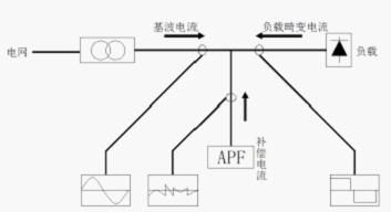
Compared with the passive filter, the active filter system has high controllability and fast response ( ≤1ms ), can compensate for various harmonics, can suppress flicker, compensate reactive power, and has one machine and multiple energy characteristics; The cost-effectiveness is more reasonable; the filter characteristics are not affected by the system impedance, and the danger of resonance with the system impedance can be eliminated; with the adaptive function, the changing harmonics can be automatically tracked and compensated. The basic principle is to detect the harmonic current from the load circuit of the harmonic source (to be compensated object), and a compensation current waveform equal to the magnitude of the harmonic current is generated by the compensation device to cancel the harmonic source load. The resulting harmonic currents cause the grid-side current to contain only the fundamental component.
ANAPF active filter device is specially designed for low-voltage power distribution systems with such characteristics. The device features high filtering efficiency, real-time tracking, and fast response. It can effectively filter out load harmonics, suppress system oscillation, and improve the stability of the power grid. Sex, while achieving significant energy saving and power supply equipment capacity increase effect.
5, ANAPF low voltage active filter in hospital construction application case
The basic status of an airport's power supply system is as follows: The power supply capacity is large, the power supply voltage is mainly 110/10/0.4KV , the airport equipment is large and dispersed, and the power consumption is large. Some of them are special equipment, and the load has certain impact. The power supply and distribution system is basically balanced in three phases, and the low-voltage part is subjected to centralized reactive power compensation.
1 Example # airfield lighting harmonic analysis station, station 1 # airfield lighting and includes two 500KVA transformer 150kVA a standby diesel generator. The main electrical equipment is airport navigation lighting equipment.
5.1 How ANAPF Active Filter Devices Work
ANAPF series active power filter means, connected to the grid in parallel, by harmonic and reactive components of the load real-time detection using PWM converter technology, and generating a reactive current component and a harmonic component from the converter corresponds The reverse component is injected into the power system in real time, so that harmonic control and reactive power compensation are achieved.
The principle is as follows:
5.2 Comparison of ANAPF active filter before and after investment
(1) Before the input of the active power filter, the distortion of the power and current waveforms is serious. After the harmonics are controlled, the waveform tends to be a sine wave, and the work of the harmonic control achieves the desired goal and effect;
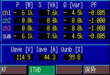
(2) The power factor waveform distortion after the input of the active power filter was significantly improved, and the values ​​before the harmonic treatment were -0.805, -1.000, and -1.000, respectively, and 0.925, 0.394, and 0.347 after the treatment.
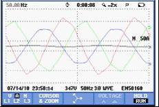
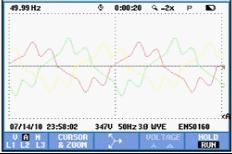
Pre-treatment current waveforms Post-treatment voltage waveforms
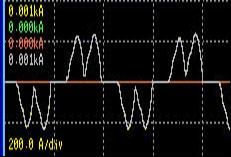
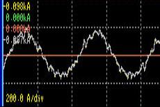
Single-phase power waveform before treatment
Single phase power waveform after treatment
 Â Â Â
  Â
Pre-treatment power factor and total distortion rate
Post-government power factor and total distortion rate
From the comparison of the drawings, we can see that: under the same load conditions, after the ANAPF active filter is put into use, the power quality is improved, but at the same time, the power is saved; the power factor is greatly increased, and the transformer and the generator are improved. The power supply capacity solves the problem of the misalignment of control equipment when the system generator runs at full load.
5.3 Installation Requirements
ANAPF is generally a standard cabinet structure. It should be avoided to be inverted or laid flat during installation. The external dimensions are determined by the selected harmonic compensation current value. The layout of the plane is generally determined by the position of the harmonic current compensation point. The layout requirements are as follows:
1) Installation from the wall: Under normal circumstances, it is recommended to arrange with the low-voltage switchgear in parallel with the wall layout, frontal operation, double-sided maintenance, and the maintenance channel at the back should not be less than 800mm.
2) Installation by the wall: ANAPF also has reliable wall layout, positive operation, and positive maintenance.
3) When considering the system wiring and plane layout, the electrical designer should pay attention to aligning the ANAPF compensation access point as close to the compensation target as possible, and be in the upstream of the sampling CT, or reserve space at the end for design and installation. The CT sampling site cannot contain downstream Capacitive load. The layout of the plane is as follows:
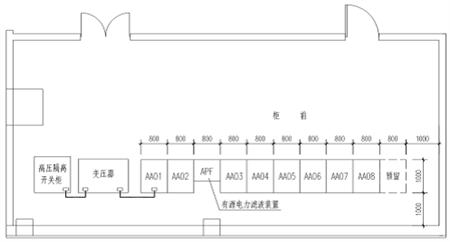
Substation layout plan
4) All metal shells of ANAPF that are not energized under normal conditions shall be properly protected against zero or protective earthing according to the grounding standard (TN-S, TN-CS, TT, etc.) of the design requirements.
5.4 Active Filter Quotation and Component List
Model Number: ANAPF100-400/B
Reference price: 120,000 yuan/set
The main product details:
No.
Name
Model number
Quantity
1
APF electrical cabinet
800X600X2200
1
2
Converter
APFCOV-CVT100
1
3
Controller
APFMC-C100
1
4
Reactor
APF-RE.(S)DG-100
1
5
Active current transformer
LT208-S7
3
6
filter
DL-1TH1
2
7
breaker
CVS160FTM160D4P3D
1
8
Contactor
LC1D150M7C
1
9
MCB
NDM1-63C32
1
10
Intermediate relay
MY4NAC
2
11
R type transformer
R320-0.38/0.22
1
12
Harmonic Detector
ACR350EGH
1
13
wire
16mm 2
Some
14
wire
4mm 2
Some
6 Conclusion
This article describes the generation and harm of harmonic sources in the airport navigation lighting system, compares the active filter device and the passive filter device scheme, and uses ANAPF active filter device to control the power supply of the airport power supply system and achieves the corresponding harmonic of the country. Standards, the power quality of the system has been greatly improved, the loss of transformers and lines has been reduced , and the power supply capacity of transformers and generators has been increased, thus solving the problem of misalignment of control equipment when the system generators are operating at full load. Greatly improved the security and economy of airport operations.
ã€references】
[1] Shanghai Ankerui Electric Co., Ltd. Product Manual. 2013.01.
[2] Harmonic Analysis of Power Supply for Civil Air Navigation Aid Lighting System. Feng Xingxue
About the Author:
Xu Shuang, female, undergraduate, Ankerui Electric Co., Ltd., the main research direction for the smart grid power distribution, Email: Mobile QQ
"AAPF Active Power Filter Device Design and Application Atlas" (atlas number: ACR13CDX701) is edited by Ankerui Electric Co., Ltd. This atlas combines the characteristics of ANAPF active power filter device products, based on electrical design specifications, research Eliminating the problem of high-order harmonics in the power supply and distribution system to achieve the goal of improving the quality of power supply and ensuring the safe operation of the power system. The Atlas is applicable to the design and modification of harmonic suppression and comprehensive management of electrical equipment in industrial, civil, and public buildings in new construction, reconstruction, expansion, and technological transformation projects. If you need atlas, please provide your organization's name, department, address, zip code, contact person, contact telephone number, email address, fax 021-69155331, mail or QQ to Ankeru Xu cream engineer, Ankerui Electric will give you a free gift. .
Shark Fork,Shark Tank Ifork,Ifork Shark Tank,Shark Pliers
TAIXING HAITAI GLOBAL TRADE CO.,LTD , https://www.jshaitship.com